When first setting up the DM-608/810 or D-4.800/6.1200 products, there is a recommended order of setting up the processor to achieve maximum performance and benefit from the processor.
They are:
First things, first. You will need to download the DM Smart DSP software from the AudioControl website. Navigate to the page for the processor you purchased then scroll to the Downloads section at the bottom of the page.
Before installing the software your processor should be powered on and connected to your computer via USB cable.
Please refer to the Knowledge Base article HERE for software installation instructions.
***SPECIAL NOTE*** At this point, you should have the DM processors inputs connected, but NOT the RCA outputs. We need to go thru all the following steps before we are ready to send audio to the aftermarket amplifiers.***
***IF AT ANYTIME THE DM PROCESSOR LOOSES CONNECTION WITH THE COMPUTER, IT IS ALWAYS RECOMMENDED TO POWER CYCLE THE PROCESSOR TO REGAIN CONNECTION***
SETTING CROSSOVERS
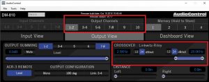
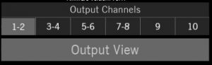
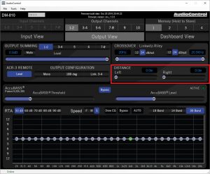
First, we want to set our crossovers for the outputs. To do this, we will be using the Output view window. We can choose between which outputs we are setting by selecting the output channel tabs at the top center of the window:
The factory default settings for the crossovers are as follows:
Channel 1-2: Highpassed at 90 Hz
Channel 3-4: Highpassed at 3.5 Khz
Channel 5-6: Highpassed at 90 Hz
Channel 7-8: Highpassed at 3.5 Khz
Channel 9: Bandpassed from 30 Hz to 90 Hz
Channel 10: Bandpassed from 30 Hz to 90 Hz
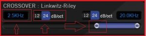
To customize these settings to fit your install, it’s as easy as either moving the slider to get the desired figure, or just typing the crossover frequency directly into the window. You can also choose between a 12 or 24 db per octave slope.
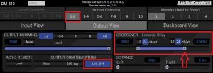
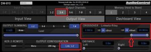
You can also “link” the crossover together for multi-way systems. With the “link” engaged, the high pass filter of one output pair will adjust the low pass filter on the linked output.
In the examples below, we’ve linked the 1-2 output with the 3-4 output via the “Link” button. As highlighted by the arrow, they now share the crossover point. By moving that point, it will then be moved on the linked corresponding output channel.
After you have set your crossovers up for all of your channels, we will then want to move to input summing. This step is mainly for OEM integration. If you are installing an aftermarket head unit, you can skip this step.
INPUT SUMMING
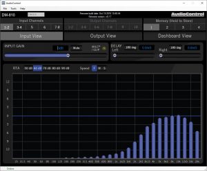
One of the great features of the DM-processor is the input and output RTA. With this feature, you can quickly determine what factory outputs are Highpassed, Lowpassed, or bandpassed so you can quickly and effectively sum channels to create a full range signal.
To determine what channels are outputting what frequencies, you would send pink noise thru the factory system. If you do not have a test CD with pink noise, you can download a wav file full of pink noise here.
Below is an example of how you would sum the factory inputs to create a full range signal:
Channel 1/2 is outputting only highs:
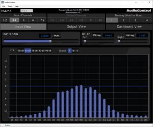
Mids on Channel 3/4:
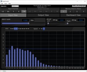
And Lows on Channel 7/8:
We can take those three inputs and Sum them using the Output Summing section by selection inputs 1/2,3/4 and 7/8 to create a full range signal
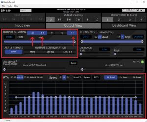
From here, you can send that same signal to all of your desired outputs by selecting the 1/2, 3/4 and 7/8 inputs on each output channel via the Output channel tabs:
For additional information, here’s a video demonstration on how summing works in the DSP:
After you have got your crossovers set, and have determined what inputs you need to sum to your output channels, it is time to set gains.
SETTING GAINS
The goal of setting the gains is to ensure that no matter the volume level on the head unit, it will be sending the adequate signal thru the processor to the aftermarket amplifiers for the best possible signal. To do this, we will want to set both the input gain and output gain for each channel.
First, we want to turn the volume on the head unit up until the MILC lights up on the channel 1-2 input:
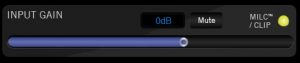
If you have a factory system that bandpasses their channel output, you will want to make sure you send the mid range signal into the 1/2 input. The MILC circuit detects distortion via the mid to low frequencies, so if you send JUST a high frequency signal to the 1/2 input, the MILC will not be able to detect distortion.
Once the MILC light turns on, we will then want to back off the volume until the MILC light turns off. Take note of where you are on the volume dial of your head unit. That is the max point you can go before distorting the output of the source head unit. The goal now is to optimize the gains within the DM-810 so you will never need to turn the volume up past this point for maximum volume.
You will then set the gains on each channel by adjusting the input gain while monitoring the maximized light on the DM-810 itself:
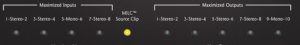
You will adjust the input gain until the maximized light begins to flicker. Once it does, back off until it is off. We do this to give us some head room on each channel
Repeat for each channel.
SETTING DELAYS
The DM-processor has the ability to set delays for every output. This allows for sweet spot adjustments for left/right, as well as front/back sound stage presentation and woofer/tweeter arrival time alignment.
You are able to adjust the output delays via the “Distance” controls for left and right. They are accessed either by
Dashboard View
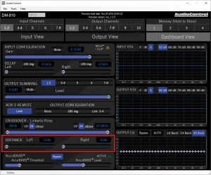
Or Output View
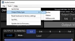
The measurement defaults to inches, but you can choose between inches, meters or Milliseconds via the “tools” drop down menu.
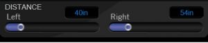
To set the output delay, you will want a measuring tape. Measure the distance from each speaker to the chosen sweet spot of the car. (Typically this is the driver’s headrest or center of the listening area).
For example, using a measuring tape, the front left door speaker is approximately 40 inches from the head rest, while the front right door speaker is 54 inches away from the head rest. So you’d punch in the values for channel 1/2 where the front left door speaker is “Left” and the right door speaker is “Right”:
You would then repeat this for each pair of channel outputs.
**NOTE** THE DISTANCE DELAY IS STORED BY PRESET, SO YOU CAN EASILY COMPARE MULTIPLE DELAY SETTINGS TO ACHIEVE OPTIMAL PERFORMANCE. YOU CAN ALSO SET PRESETS FOR DIFFERENT PASSENGER CONFIGURATIONS, SUCH AS A CAR THAT ONLY HAS A DRIVER, VERSUS A CAR WITH A DRIVER AND 3 PASSENGERS
After the delays are set, you are ready to EQ
SETTING EQ
The DM-processor has a great feature called Auto-EQ. It is a great tool for factory integration. It will quickly and accurately undo the pre-installed EQ curve from a factory system for a flat frequency response.
To run the Auto-EQ, you will need to send Pink Noise thru the system. If you do not have a test CD with pink noise, you can download a wav file full of pink noise here
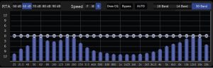
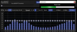
The example below shows the factory system outputting a signal that has a boost both on the high and low end.
Press the “Auto” button, the processor will make it’s initial pass
A warning message will pop up
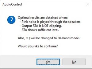
Click “Yes”. It will then process the EQ.
And then will ask to accept the changes
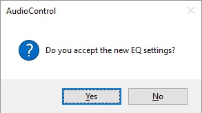
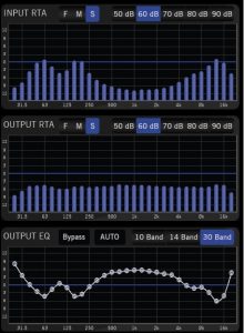
It is recommended you run the Auto EQ function 3 times to get a relative flat response. The result should look something like this:
We are now ready to hook up your amplifiers to the outputs of the DM-processor
If the overall volume is still not as loud as it could be, you will then adjust the input gains on the amplifier for maximum effect.